Domenic Landriscina

Mechanical engineering, University of Maryland

DomenicLandriscina

Look through the blinds to see some of my projects.

About me

Studying
Mechanical engineering at the University of Maryland, class of 2029
Skills
CAD, PCB design, 3D printing, electronics
Interests
Robotics and product design

Senior year
2024–25

A window blind that automatically opens in the morning

Press the green button before bed. Eight hours later the slats open, and daylight gently wakes you up.

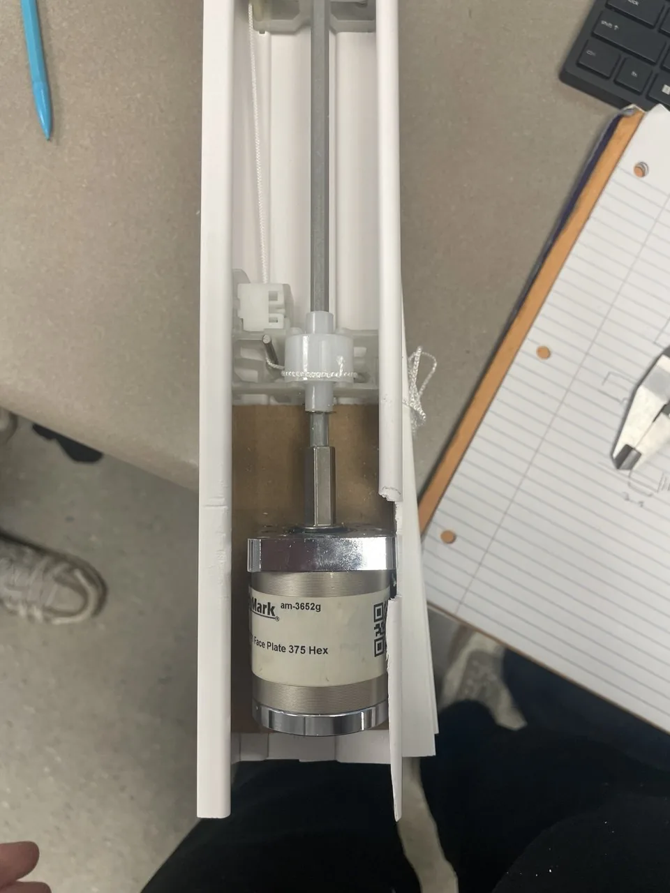
  • A 12 V motor drives a planetary gearbox that sits in the end of the head rail and turns the tilt mechanism directly.
  • An Arduino Uno with an Adafruit Motor Shield runs the timer and controls the motor.
  • The Arduino sets the slat angle accurately by reading the motor's encoder.
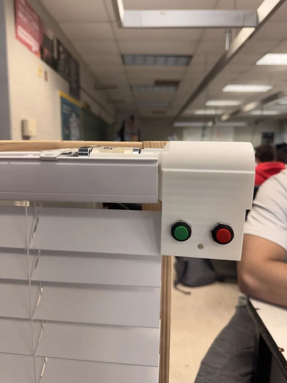
  • The green button starts the timer, the LED confirms it has started, and the red button closes the blind.
  • Senior design
    project
  • Catonsville
    High School
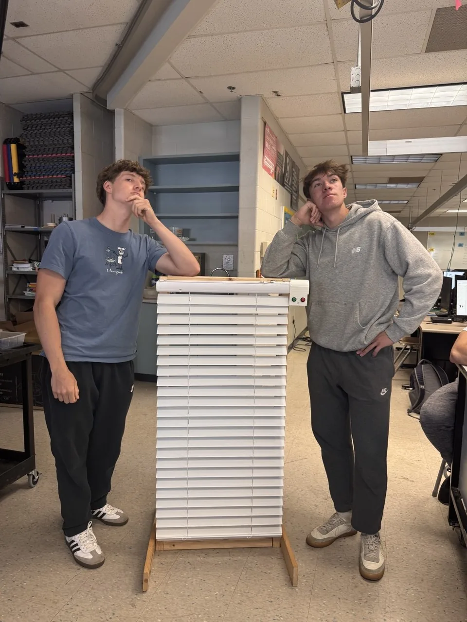
The prototype on its test stand. For the demo, the eight-hour delay is cut to one second.
Taken apart

Parts

  1. 1
    Head rail and slats
  2. 2
    Shaft adapterSlides over the large hex shaft on the gearbox. The blind's smaller hex rod slides into the other end, which couples the two.
  3. 3
    Planetary gearbox and 12 V DC motor
  4. 4
    Motor housing and control panel
  5. 5
    Buttons and LEDWired to the control box.
  6. 6
    Arduino Uno and Motor ShieldThe shield plugs directly into the top of the Uno.
  7. 7
    12 V battery packPlugs into the motor shield.
  8. 8
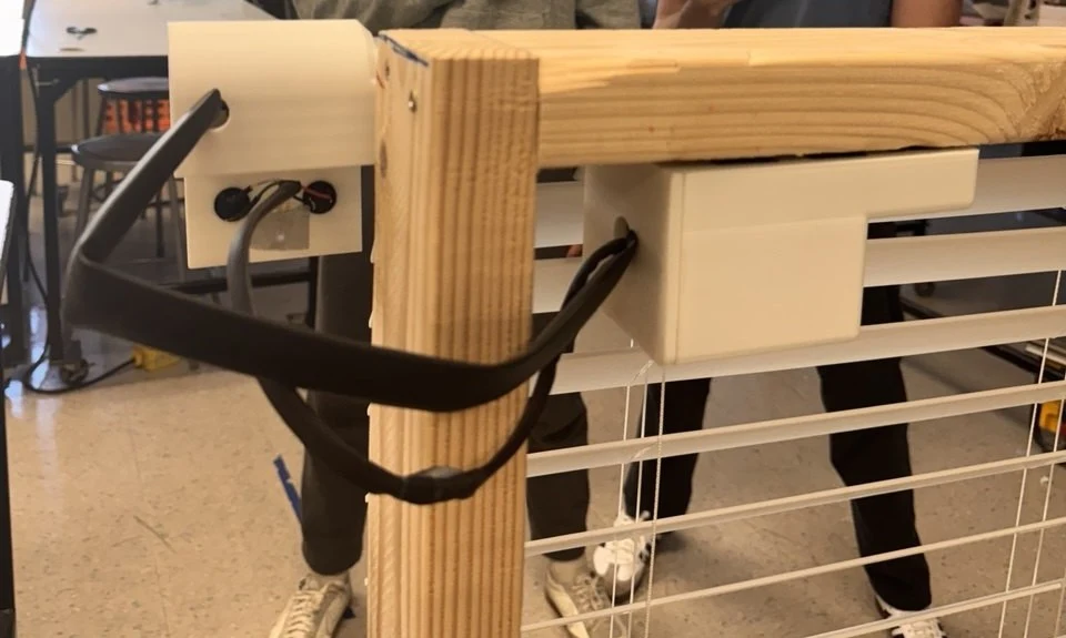
    Electronics enclosure3D printed, with an end cap. Tucked up under the top of the window opening, behind the blind.
  9. 9
    Window frame
Looking down into the head rail: a silver gearmotor with a hex shaft coupled to the white tilt mechanism
Testing the fitment of the gearbox.
White 3D printed button box with a green and a red button, at the end of the blind's head rail beside the slats
Front view: start and stop buttons, plus an indicator light.
The test stand from behind: the back of the button box, a white printed box fixed under the top beam, the cable between them, and the slats
From behind: the enclosure under the top beam, and the cable to the buttons.
Two students leaning on the finished blind and its wooden test stand in a classroom
The finished prototype.

Spring 2026

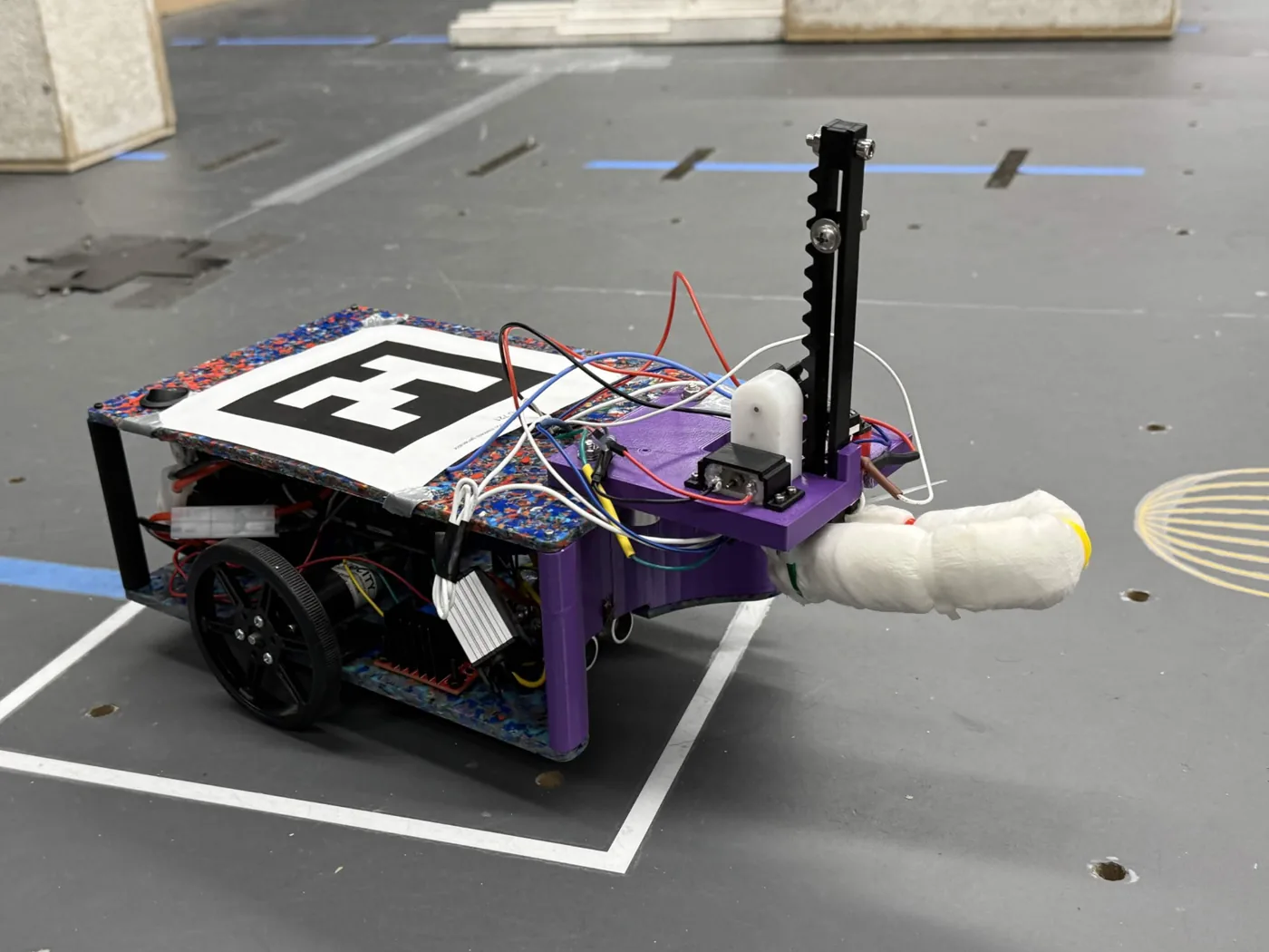
My team's OTV

Taken apart
  • Built in my intro to engineering class (ENES 100) with a team of eight, in one semester.
  • Our job: drive autonomously to the mission site, detect the water level and whether there were pollutants, then collect a water sample and navigate to the finish.
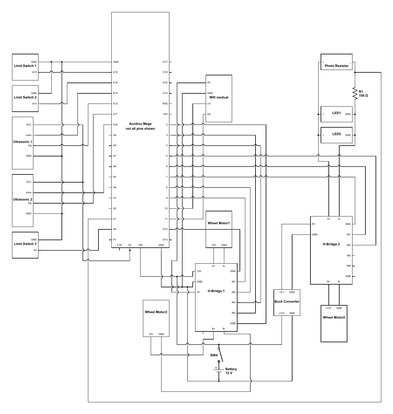
  • I was the electronics lead, working mainly on the electronics, the power distribution and the early CAD.
  • One 12 V battery feeds two H-bridges. One is left at 12 V, and the other uses a buck converter to drop it to 5 V. The two H-bridges then power everything.
  • We used sodium polyacrylate (from a diaper) to soak up enough water.
What I learnedOn a tight timeline, everything that can go wrong will.
A mission run at double speed.
The finished rover in the arena, with its marker on top, the rack raised and the diaper out in front
The finished rover in the arena.
Circuit diagram: an Arduino Mega wired to three limit switches, two ultrasonic sensors, a Wi-Fi module, two H-bridges, a buck converter, three motors, a photoresistor, two LEDs, a switch and a 12 V battery
My circuit diagram.
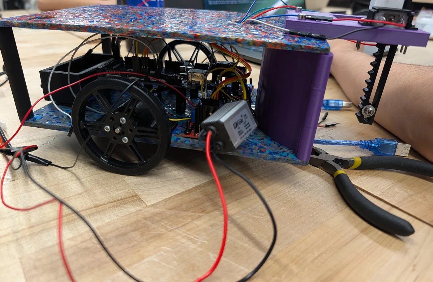
The rover on a bench part way through wiring, with the two plates, a wheel, the water shield and loose red and black leads
A wiring test, running from a bench supply.

February to
July 2026

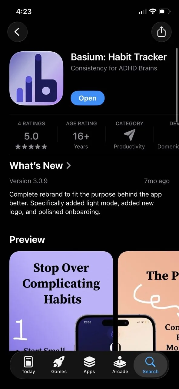
Basium, a personal productivity app

  • A habit tracker built on streaks, coming from how I made habits in high school.
  • Took me about two months to build and ship, after many redesigns.
  • A streak counter, a calendar history and challenge paths that keep you coming back.
  • Marketed it on TikTok and Reddit. A few thousand views in total.
  • My first app, PickyPal, was easy to market because it solved a real problem in a niche market. Habit trackers are a crowded category, and mine was not different enough.
38downloads
$20in sales
5.0on the App Store, 4 ratings

As of November 2026.

What I learnedStarting is the hard part. Once you are good at that, you need to start the right things.
Basium, recorded on my phone.
Basium: Habit Tracker on the App Store, rated 5.0 from 4 ratings
The App Store listing.

July 2026
to now

My four-legged walking robot

Taken apartLoading the CAD model…
  • The whole body was designed in SolidWorks, then printed on my Bambu Lab A1.
  • 8+ design iterations and counting.
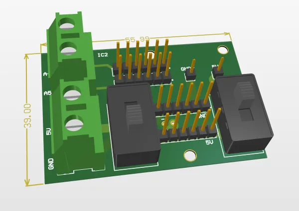
  • For the power distribution and I2C bus, I designed my first simple PCB in Altium Designer.
  • An Arduino Nano controls the PCA9685 servo driver and two OLED displays, which act as the eyes.
  • Currently the robot runs a static trot gait, with different animations coded in.
What I learnedBringing a digital design to real life is the most rewarding part of the design process.
Clearly not enough traction walking on tile.
Testing a new foot design that did not work at all.
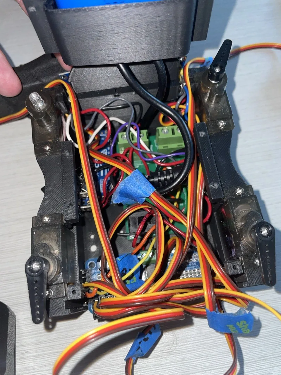
Inside the robot body: servo wires, the custom board and the driver packed into a small space
The space problem that made assembly hard.
3D render of the custom power and I2C board, 55 by 39 millimeters
Custom power and I2C board, 55 × 39 mm.

Next

Rebuild the robot and open-source it

Version two should be good enough to teach someone else the basics of robotics.

  • An ESP32 instead of the Arduino Nano, so it can be driven with an Xbox controller.
  • An IMU to measure its orientation and feed that data into the controls.
  • CAD that prints with fewer supports and goes together easily.
  • A smaller custom PCB.
  • New feet with better traction.
  • Firmware that makes new animations and leg calibration simple.
  • The overall goal is to release the files and let other people build and iterate on my designs.
Version two targets
ControllerESP32
Target parts cost$100
Build videos1 per week
Ship dateDecember